Pneumatic systems are easily created from standard components to deliver a dependable compressed air supply and produce economical motion at machinery, equipment and actuators.
Pneumatic systems are commonly used for creating linear and rotational motion in many kinds of machinery and equipment applications. These systems are assembled from a variety of standard components and use compressed air to achieve controlled motion.
There are other motion control options which may be used instead of or in conjunction with pneumatics. Hydraulics is also a fluid power technology, and it uses uncompressible liquids and can achieve greater forces. Electricactuators can provide more accurate control. However, both are more expensive than pneumatics, and require more maintenance.
Pneumatic systems maintain a well-deserved reputation for offering an excellent combination of compact size, good power availability and reliable operation. These systems can be relatively simple and cost-effective to design, install and maintain compared to other options. This article examines some of the fundamentals necessary to create a pneumatic system.
Pneumatic Parts
Any pneumatic system uses one or more of the following elements: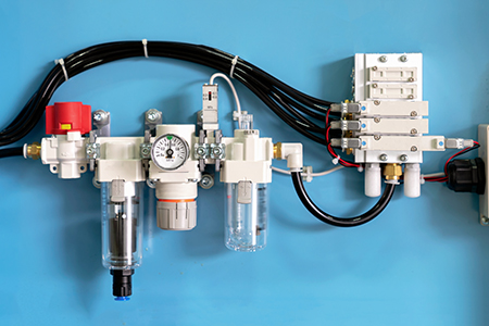
- Air Supply Compressors and Storage Tanks
- Air Filters, Dryers, Lubricators and Pressure Regulators
- Tubing, Hoses and Fittings
- Control Valves (Individual and/or Manifold Assemblies)
- Flow Controls and Silencers
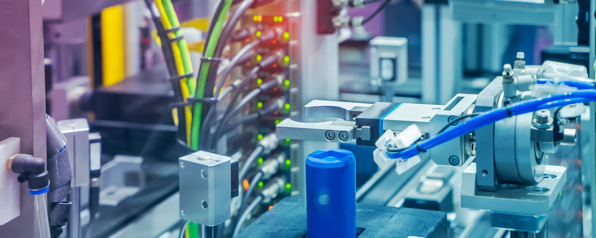
- Linear Actuators including Cylinders, Slide Tables, Rotary Actuators and Grippers
- Logic Elements
- Instrumentation
Air Supply
Air supply systems are generally compressors, which must be sized to supply a cubic feet per minute (CFM) volume sufficient for all the usage points. There are often several compressors in parallel for redundancy, and they may use alternating start schemes to balance the load. Compressed air can also be connected to storage tanks so the compressors cycle on/off less often. Pneumatic control systems typically use operating pressures between 20 to 130 pounds per square inch (psi). Normally the main line is the highest pressure, which is then stepped down progressively as required for control valves and point of use tools.
Air Filters, Dryers, Lubricators and Pressure Regulators
These components may be used at a main upstream location and also downstream at usage points, and they are collectively called air preparation or treatment devices. All air preparation devices serve to protect sensitive downstream components. A variety of filters are available to remove dust, dirt, moisture and compressor oil. Dryers are used when needed to lower the dew point. Pressure regulators maintain a consistent downstream pressure so equipment can operate reliably regardless of the upstream pressure. Some downstream equipment, such as high-speed rotating tools, require a small amount of oil in the air which can be provided by lubricators. Multiple functions may be combined into one device such as a filter/regulator/lubricator (FRL).
Tubing, Hoses and Fittings
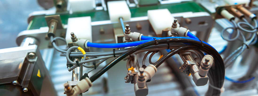
Main compressed air pressure is usually routed through pipes. Metal tubing can be used on drop points off the main line when strength and rigidity is needed, but if pressure ratings allow, then flexible tubing and hoses can be run to the points of use. Bulkheads can be selected to quickly connect/disconnect multiple tubing points at one time to facilitate maintenance, while manifolds are a convenient way to distribute many tubing connections. Fittings can be classic threaded, or the much more popular one-touch push connect style. However, it is always important to ensure that matching metric or English sizes are chosen.
Control Valves
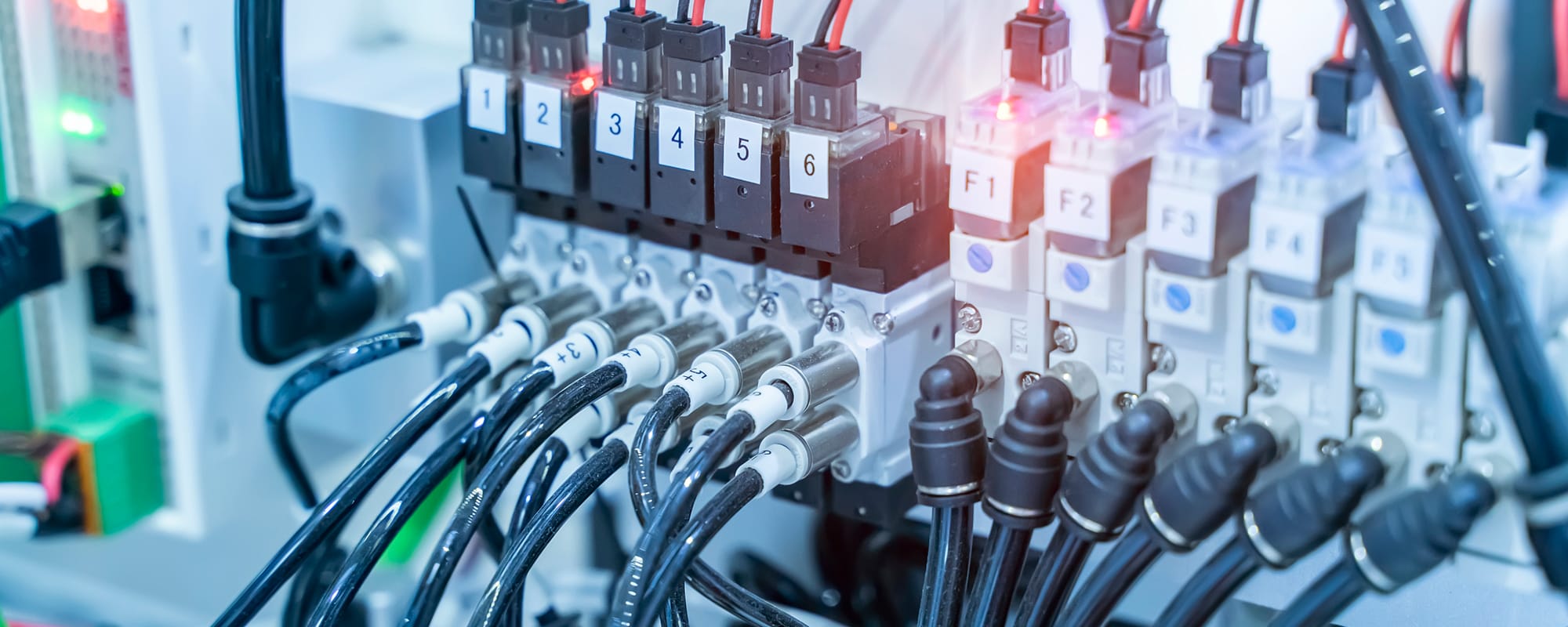
Pneumatic control valves will be explored in greater depth with another article. There are several types including manual/mechanical, individual electrical solenoid and multiple manifolded. Manual types are used by service personnel, while mechanical types used to sense positions for pneumatic logic on a machine. Electric solenoid valves, whether individual or ganged in manifolds, are most suitable for automatic control.
Flow Controls and Silencers
Flow controls and silencers are accessories for optimizing and improving equipment operation. Flow controls allow the speed of motion to be individually controlled in each direction. Silencers reduce the sound of exhausting air to provide a quieter operating environment.
Cylinders, Slide Tables, Rotary Actuators and Grippers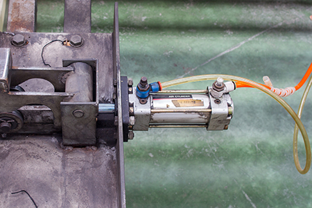
All pneumatic actuators convert air pressure into physical motion. These will also be covered in more detail in another article. Most popular are cylinders, slide tables, rotary actuators and clamps/grippers for motion applications, and quarter-turn actuators to control process valves. These devices come in many sizes and shapes and must be carefully coordinated with the mechanical design. Also, these devices, and how often they operate, determine the required supply of compressed air.
Logic Elements
Although it’s possible to pneumatically perform logic, such as AND and NOT, with the proper components, this type of functionality has largely been superseded by PLC and relay-based automation of electrical solenoids. Some recent designs use PC based programming.
Instrumentation
When automating pneumatic systems, instruments are often incorporated into the control system to provide feedback. For instance, pressure switches can ensure that proper air pressure is present, while position sensors can be used to confirm actuator positioning.
Pneumatic Systems
With a basic understanding of the pneumatic components described in this article, users can create an endless variety of manual and automatic pneumatic systems. Detailed calculations are a good idea and often necessary, however using common sense and ensuring that equipment and fitting sizes are matchedmay suffice.




This guide is super helpful! I’ve always been curious about how hydraulics and pneumatics work but found it a bit intimidating. Breaking down the basics makes it so much easier to grasp. Can’t wait to try out some of these concepts in
Check out this post: Understanding the Basics of Hydraulics and Pneumatics: A Beginner’s Guide
This guide is super helpful! I’ve always been curious about hydraulics and pneumatics but felt overwhelmed. Love how it breaks down the basics—it makes things so much clearer. Can’t wait to dive deeper and see how I can apply these concepts
Check out this post: Understanding the Basics of Hydraulics and Pneumatics: A Beginner’s Guide
This is a fantastic starting point for anyone curious about hydraulics and pneumatics! I’ve always found it fascinating how these systems power so much of what we use daily. Can’t wait to dive deeper into the applications—I had no idea how vital
Check out this post: Understanding the Basics of Hydraulics and Pneumatics: A Beginner’s Guide
Great post! Hydraulics and pneumatics are super interesting yet often overlooked. I love how you broke down the basics—definitely makes it easier for beginners to grasp. Can’t wait to explore more about their applications in different industries. Keep
Check out this post: Understanding the Basics of Hydraulics and Pneumatics