Traditional sensors and actuators use basic hardwired connections, but IO-Link offers a way to extend functionality and take advantage of smart sensors without complicated wiring.
A fundamental feature of industrial automation controllers is the ability to process input and output (I/O) signals. Inputs are sent to controllers from analog sensors like pressure transmitters or discrete sensors like position switches. Outputs are sent from controllers to analog devices like valve positioners or discrete devices like solenoids.
Traditionally I/O is hardwired to PLC input cards. Analog signals commonly operate at 24 Vdc and range from 4 to 20 mA, while discrete signals may be at 120 Vac or 24 Vdc on/off, although 24 Vdc is becoming most prevalent due to the inherent safety of lower voltage. Standard devices are constrained by the limited data they can signal over hardwired signals, usually just on or off for a discrete signal and the process variable measurement for an analog signal.
However, field devices are becoming much smarter. Photoeyes, proximity switches, pressure switches and more can send multiple measured variables, along with enhanced configuration and diagnostics information. Over the years, engineers have worked to improve the amount of information that can be transmitted over existing wiring through the use of superimposed signals.
This article discusses how IO-Link technology makes traditional hardwired sensor and actuator wiring much more capable by adding a superimposed signal for connections to IO-Link smart field devices.
Why Use IO-Link?
IO-Link offers many benefits. Users will find the advantages in design, commissioning, reliability and maintenance, all of which reduce costs when implementing automation systems with IO-Link:
- Manufacturer agnostic; users have more options
- Reduced wiring saves money
- Modular and scalable
- Increased data available
- Analog values can be transmitted digitally
- Reduced installation time
- Standardized point-to-point wiring with M12 and M8 3-wire cables
- Software configuration makes startup faster
- Reduced downtime
- Resistant to electrical noise
- Remote configuration and monitoring
- Increased advanced diagnostics
- Simple plug-and-play device replacement
- Supports predictive maintenance efforts
Since IO-Link is modular, scalable and largely backward compatible with hardwired systems — and because so many IO-Link devices are now available — it’s easy for users to try out the system on a new project.
Hardwired Limitations
The limited nature of standard hardwired signals was mentioned above. Also, each of these signals requires a specific I/O module on the control system, or a more expensive multiplex module that can accept/generate multiple signals. The hardwiring needs to be home-run from each field device back to the nearest controller or remote I/O location. The main benefit of hardwiring is simplicity, and the fact that if wiring to any one field device fails, the other field device signals are usually not impacted. The leading exception is when multiple analog devices are connected to a 4-20mA current loop.
Digital Costs and Complexity
Digital communications, on the other hand, are much more capable. For industrial applications these are collectively called fieldbus networks and will be covered in other articles. These transfer large amount of data quickly, much like Ethernet or USB on a home computer, but come with substantial costs and complexity.
Superimposed Signal Advantages
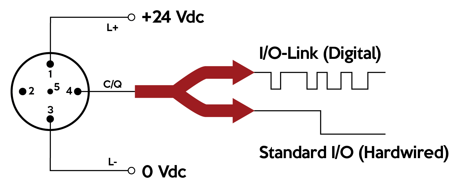
A hybrid solution maintains standard industrial hardwiring while superimposing additional digital communications to gain the additional benefits. The data rates (communication speed) are far less than Ethernet, but ample for most industrial applications. Highway addressable remote transducer (HART) technology has been available for many years as a way of doing this for analog signals.
More recently than HART, a similar technology called IO-Link has been gaining momentum to superimpose digital communications over standard I/O wiring so users can economically implement reliable and high-performance I/O connections. These connections even enable traditional discrete sensors to also send analog information.
IO-Link Basics
IO-Link is an internationally standardized I/O signaling technology described by IEC 61131-9 and supported by a consortium of over 150 companies. These companies make automation controllers, sensors and connecting devices compliant with the IO-Link standard. IO-Link technology is marketed as universal, smart and easy to use. Products from different vendors are compatible and connections are standardized.
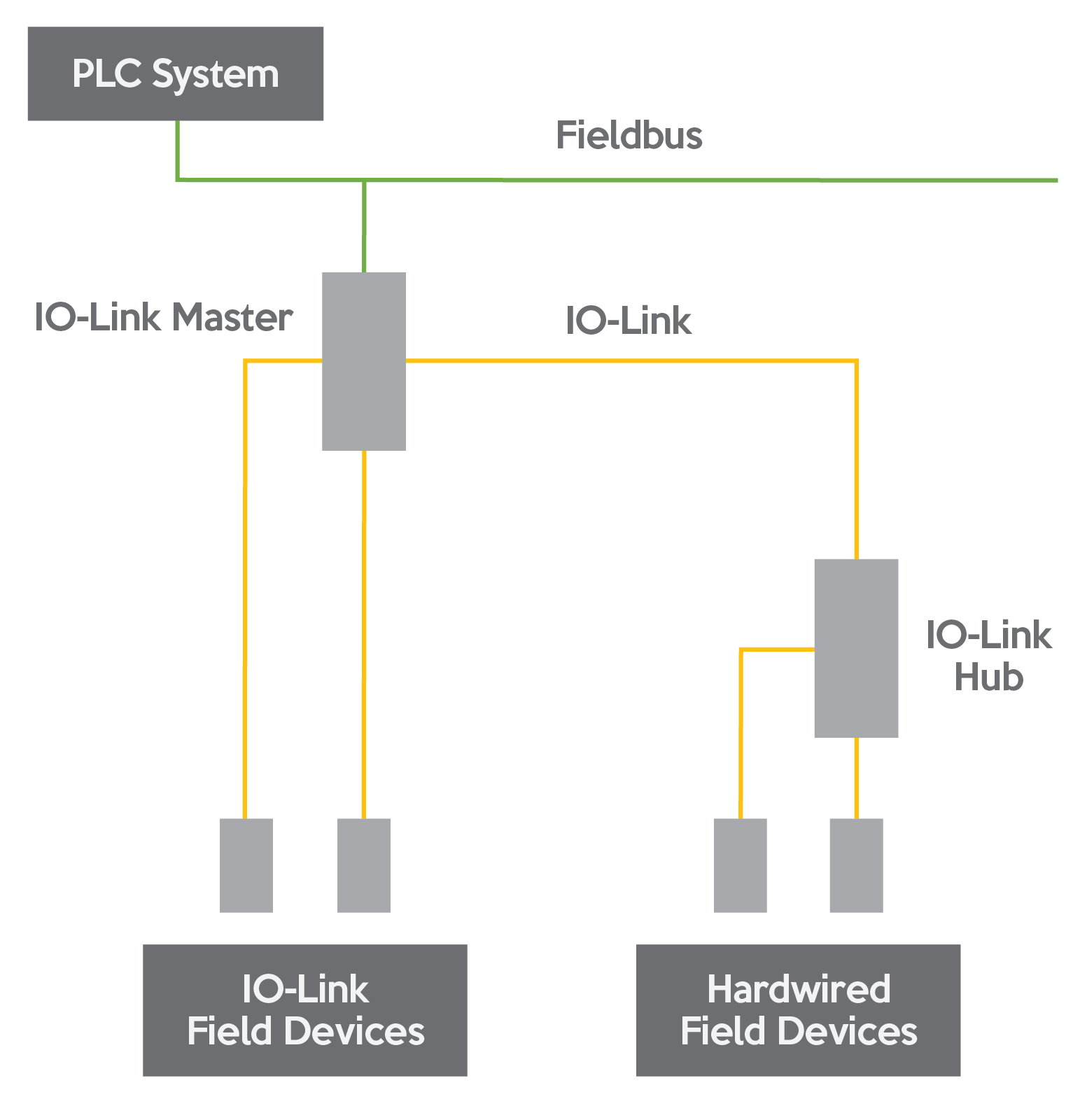
The technology is point-to-point communications, not a fieldbus or other type of network. An IO-Link “master” is a device that can interact with several standard I/O or IO-Link field devices. A typical IO-Link architecture uses masters to translate this information up to a fieldbus so higher-level controllers can interact with the field devices. Some vendors offer IO-Link I/O modules for connecting multiple standard I/O devices and consolidating them into one IO-Link connection.
Data transfer rates for the IO-Link protocol can be 4.8, 38.4, or 230.4 kBaud, each with two-way communications. Master devices support all speeds, but field devices operate at just one of the speeds. Up to 32 bytes of input and output data may be transferred per each device based its capabilities. There are limitations, but dozens or hundreds of devices can be connected on IO-Link.
IO-Link Connections
Connections for IO-Link devices are plug-and-cord type, most using standard M12 5-pin connectors. Components are available with IP65/67/69 ratings and are quite compact so they can be located close to or on equipment. Up to five pins are needed, and the cables are unshielded and must be less than 20m long.
There are two types of connection Classes (also known as Types). They are generally interchangeable, but device-specific uses of pins 2 and 5 must be evaluated. Up to 200mA of power can be supplied to field devices.
Class A devices need just 3 pins: 1 is +24 Vdc, 3 is 0 Vdc (ground), and 4 is the communication pin. However, manufacturers may choose to use pin 2 as a standard input or output.
Class B devices have a similar pinout but offer isolated power and ground on pins 2 (+24 Vdc) and 5 (0 Vdc) for cases where field devices require higher power.

